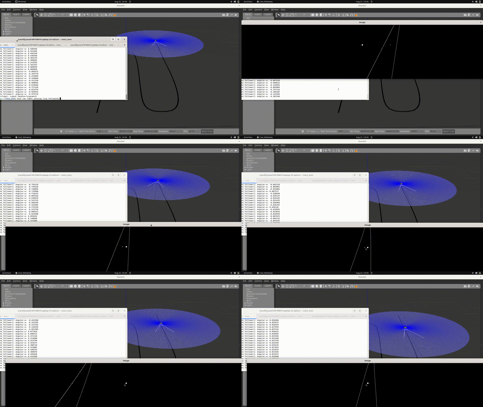
Line Following Robot using PID Controller
PID Controller Implementation for Line Following Robot

Overview
This project implements a line-following robot using computer vision techniques with OpenCV and a PID controller in ROS2. The robot uses camera input to detect a line on the ground and adjusts its movement to follow the line accurately. The implementation includes:
- Image processing to detect edges and identify the line.
- A PID controller to adjust the robot’s steering based on the detected line position.
- Integration with ROS2 for subscribing to camera data and publishing movement commands.
Project Structure
line_follower/
├── CMakeLists.txt
├── package.xml
├── models
│   └── line_track
│   │   └── model.config
│   │   └── model.sdf
│   └── maze
│   │   └── model.config
│   │   └── model.sdf
│   └── meshes
│       └── base.dae
│       └── line.dae
├── launch
│   └── line_world.launch.py
├── src
│   └── linefollowing.cpp
- CMakeLists.txt: Build configuration.
- package.xml: Package metadata and dependencies.
- params.yaml: Configuration file for parameters.
- launch/: Contains launch files to start the node.
- src/: Source code for the node.
- models/: World models which built on Gazebo and 3D meshes file.
Implementation Details
How I Built the System:
Set Up the Workspace and ROS2 Packages: I began by creating a new ROS2 workspace and set up the necessary package structure. This included creating directories such as
launch,include, andsrcto organize the code and resources effectively.Install and Add Necessary Libraries: I installed and included essential libraries required for the project. These included
geometry_msgs,sensor_msgs,std_msgs,rclcpp, and OpenCV. These libraries are crucial for handling ROS messages and performing image processing tasks.Create the Node Source File (
task1.cpp): I created a C++ source file namedtask1.cppwhere I implemented the main functionality of the line-following node with a PI controller.- Include Necessary Headers: In
task1.cpp, I included the necessary headers at the top of the file:#include "rclcpp/rclcpp.hpp" #include "geometry_msgs/msg/twist.hpp" #include "sensor_msgs/msg/image.hpp" #include "std_msgs/msg/string.hpp" #include <opencv2/opencv.hpp>These headers provide access to ROS2 functionalities and OpenCV image processing capabilities.
- Define the
LineFollowingClass: I defined a class namedLineFollowingthat inherits fromrclcpp::Node. This class encapsulates all the methods and variables required for the line-following functionality.class LineFollowing : public rclcpp::Node { public: LineFollowing(); private: // Member variables and methods }; - Initialize Publishers and Subscribers: Within the class constructor, I initialized a publisher to the
/cmd_veltopic to send velocity commands to the robot. I also set up a subscriber to the/camera/image_rawtopic to receive real-time images from the robot’s camera.cmd_vel_publisher_ = this->create_publisher<geometry_msgs::msg::Twist>("/cmd_vel", 10); image_subscription_ = this->create_subscription<sensor_msgs::msg::Image>( "/camera/image_raw", 10, std::bind(&LineFollowing::camera_callback, this, std::placeholders::_1)); - Implement Callback Methods: I implemented the
camera_callbackmethod, which is triggered whenever a new image is received from the camera. Inside this callback, I called several helper methods:transferData: Converts the incoming ROS image message to an OpenCVMatobject for processing.edgeSegmentation: Applies image processing techniques to detect edges and segment the line in the image.robotAction: Calculates the control signals using the PI controller based on the processed image.visualization: Displays the processed images for debugging and visualization purposes.void camera_callback(const sensor_msgs::msg::Image::SharedPtr msg) { cv::Mat frame = transferData(msg); cv::Mat segmented = edgeSegmentation(frame); robotAction(segmented); visualization(segmented); }
- Define Timing Variables for the Controller: I introduced variables to calculate the time difference
dtbetween iterations, which is essential for the integral component of the PI controller.rclcpp::Time previous_time_; double dt_;In the callback, I calculated
dt_:rclcpp::Time current_time = this->now(); dt_ = (current_time - previous_time_).seconds(); previous_time_ = current_time; - Configure PI Controller Parameters: In the class constructor, I declared and initialized the PI controller parameters
KpandKialong with anintegral_error_variable.double Kp_; double Ki_; double integral_error_; LineFollowing() : Node("line_following"), Kp_(0.5), Ki_(0.1), integral_error_(0.0) { // Initialization code } - Implement the PI Controller Logic: In the
robotActionmethod, I implemented the PI controller logic to compute the control signal based on the error between the desired line position and the current position.void robotAction(const cv::Mat &segmented_image) { double error = computeError(segmented_image); integral_error_ += error * dt_; double control_signal = Kp_ * error + Ki_ * integral_error_; sendVelocityCommand(control_signal); } - Create the
mainFunction: I wrote themainfunction to initialize the ROS2 node and start spinning, allowing it to process incoming messages continuously.int main(int argc, char * argv[]) { rclcpp::init(argc, argv); auto node = std::make_shared<LineFollowing>(); rclcpp::spin(node); rclcpp::shutdown(); return 0; } Modify the
CMakeLists.txtFile: I updated theCMakeLists.txtfile to include all necessary dependencies, libraries, and executable targets. This ensured that the code compiled correctly and all dependencies were linked properly.- Compile and Run the Node: Finally, I compiled the package using
colcon buildand ran the node to test the line-following functionality with the PI controller in a simulated environment.
How I Performed the PI Control Analysis:
Tune the PI Controller Parameters (
KpandKi): I experimented with different values of the proportional gainKpand the integral gainKito observe how they affect the robot’s ability to follow the line smoothly. By adjusting these parameters, I aimed to minimize overshoot and steady-state error while ensuring quick response to changes in the line’s position.Analyze System Response: I monitored the robot’s performance in various scenarios, such as straight lines, curves, and sharp turns. This helped me understand the impact of the PI controller on the robot’s navigation and make necessary adjustments to the controller parameters.
Test Under Different Conditions: I tested the system under different lighting conditions and backgrounds to ensure robustness. This involved adjusting image processing parameters in the
edgeSegmentationmethod to maintain reliable line detection.
By following these steps, I successfully enhanced the camera-based line-following system by integrating a PI controller, resulting in improved performance and smoother navigation along the line.
Project Summary
Image Processing
- Grayscale Conversion:
- Simplifies the image data by removing color information.
- Canny Edge Detection:
- Detects edges in the image by looking for areas of rapid intensity change.
- Region of Interest (ROI):
- Focuses processing on a specific part of the image (e.g., the bottom half) where the line is expected to be.
- Edge Detection within ROI:
- Searches for white pixels (edges) in the ROI to identify the line’s position.
PID Controller
- Proportional (P):
- Corrects the error based on the current difference between the robot’s center and the line’s midpoint.
- Integral (I):
- Accumulates past errors to eliminate steady-state error.
- Derivative (D):
- Predicts future error based on the rate of change, improving stability and response time.
- Anti-Windup Mechanism:
- Prevents the integral term from accumulating excessively when the controller output is saturated.
Robot Control
- Linear Velocity:
- Set to a constant value to move the robot forward.
- Angular Velocity:
- Adjusted based on the PID controller output to steer the robot towards the line.
Using the Package
1. Prerequisites
- ROS2 installed (e.g., Humble, Foxy, Galactic).
- OpenCV installed and available in your ROS2 environment.
- A robot simulation or physical robot equipped with a camera publishing to
/camera/image_raw.
2. Build the Package
cd ~/ros2_ws/src
git clone https://github.com/badriawan/robotics_software_engineer.git`
colcon build --packages-select module_5_assignment
source install/setup.bash
3. Run the Node
Using the Launch File
ros2 launch module_5_assignment line_follower.launch.py
Using the Rqt Reconfigure to Set The Best Param
ros2 run rqt_reconfigure rqt_reconfigure
4. Visualization
- OpenCV Window:
- The node will display the ROI with markers showing the line’s midpoint and the robot’s center.
- RViz2 (Optional):
- Visualize the robot’s movement and sensor data.
5. Parameter Tuning
Adjusting Parameters:
Modify params on rqt_reconfigure to fine-tune the controller:
lower_threshold: 200  # Canny edge detection lower threshold
upper_threshold: 250  # Canny edge detection upper threshold
Kp: 0.001             # Proportional gain
Ki: 0.0               # Integral gain
Kd: 0.0               # Derivative gain
Conclusion
This project demonstrates how to implement a line-following robot using OpenCV for image processing and a PID controller for movement adjustment within the ROS2 framework. By processing camera images to detect a line and adjusting the robot’s steering accordingly, the robot can follow a path autonomously.
Key Takeaways:
- Integration of Computer Vision and Control:
- Combining image processing with control algorithms enables robots to interact intelligently with their environment.
- ROS2 Capabilities:
- ROS2 provides a robust framework for robotics applications, facilitating communication between sensors and actuators.
- PID Controller Tuning:
- Proper tuning of the PID controller gains is essential for optimal performance.
Next Steps:
- Enhancements:
- Implement adaptive thresholding to handle varying lighting conditions.
- Introduce a more sophisticated line detection algorithm (e.g., Hough Transform).
- Real-world Testing:
- Deploy the system on a physical robot and test in different environments.
- Obstacle Avoidance:
- Integrate obstacle detection to allow the robot to navigate around objects while following the line.
References
Feel free to clone the repository, test the code, and modify it to suit your specific needs. If you encounter any issues or have questions, please open an issue on the project’s GitHub repository.
